Electrical Power System
1. Design Focus
For EPS, it is important to consider the following specs of batteries and parts.
- Voltage
- Max Current
- Discharge Rate
- Capacity
2.Concept Design
2.1 Schematic
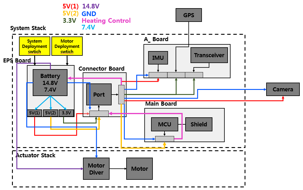 Figure 1. Overall Schematic
The above diagram is v.3.0 schematic for all system. The concept cannot be understandable without other systems because EPS should consider all the details specs of parts. Only the small EPS Board diagram is for EPS system. The overall systems can be divided to 2 Stacks, System Stack and Actuator Stack.
Figure 1. Overall Schematic
The above diagram is v.3.0 schematic for all system. The concept cannot be understandable without other systems because EPS should consider all the details specs of parts. Only the small EPS Board diagram is for EPS system. The overall systems can be divided to 2 Stacks, System Stack and Actuator Stack.
 Figure 2. EPS diagram
First, System Stack is main system deal with MCU consist of main sensors, IMU, GPS, Transceiver, Camera. Mainstream communications and operations are processed on these systems so they don’t require much voltage but proper capacity. System stack uses 7.4V battery and uses LDO regulators convert to 5V and 3.3V.
Second, Actuator Stack is driving system, literally with motors. As the system holds all body and drives it, it requires large current and capacity. Actuator Stack uses huge 14.8V battery directly to motor driver.
Figure 2. EPS diagram
First, System Stack is main system deal with MCU consist of main sensors, IMU, GPS, Transceiver, Camera. Mainstream communications and operations are processed on these systems so they don’t require much voltage but proper capacity. System stack uses 7.4V battery and uses LDO regulators convert to 5V and 3.3V.
Second, Actuator Stack is driving system, literally with motors. As the system holds all body and drives it, it requires large current and capacity. Actuator Stack uses huge 14.8V battery directly to motor driver.
3.Detail Design
EPS is the main Power Supply System for all parts of Satellites. So all the electrical specific details of the parts should be considered when it is designed. There are keypoint focuses in each of design steps. You can see the minimalized designing steps below.
3.1 Selecting Batteries
In Electrical System battery seems like a pump in canal system. As the pump in canal makes the force that water can flow, battery also makes the current. So the battery let all the circuits worked. However the problem is if there are many loads in circuit system, the pump should be overloaded. So we should select proper batteries for system. There are 4 points that we consider for selecting batteries. Voltage, Max Current, Discharge Rate, Capacity. The reason we considered these is so many parts and the torque of motor. In our satellite we selected 14.8V for motors and 7.4V for other systems. This step is proceeded with checking parts of other system due to the analysis of specification. The focalizing of specification is needed because the parts influence the process most.
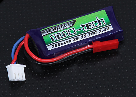 Figure 3. Turnigy nano-tech 300mah 2S 35~70C Lipo Pack(7.4V Battery)
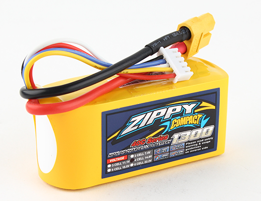 Figure 4. ZIPPY Compact 1300mAh 4s 40c Lipo Pack(14.8V Battery)
- Voltage Parts Rated voltage Odroid U3(MCU) 5V My ahrs+(IMU) 5V MAX-6Q(GPS) 3.6V ESP8266(Wi-Fi) 3.3V Webcam(CAM) 5V
The battery’s voltage should not be smaller than any of the max voltage of parts. In this part the content should be focused on is the availability. At first time we use 11.1V(3S) for overall system but the problems for driving we changed it to 14.8V(4S). The shut-down problem for MCU rises, nevertheless. So we add 7.4V(2S) for overall systems except Motor. Finally we picked 14.8V for Motor Power because of the torque. And 7.4V was for other systems because they use 5V or 3.3V for Vcc.
- Max Current Parts Current consumption Odroid U3(MCU) 2A My ahrs+(IMU) 52mA MAX-6Q(GPS) 25mA ESP8266(Wi-Fi) 0.3A Webcam(CAM) 0.27A
It is important to compare the max current of battery and Sum of the current consumption of circuits. If the Sum of the current consumption exceeds max current, the battery can act like a bomb due to its chemical action. As most of the batteries have huge max current, we didn’t spend much time about this.
Discharge Rate The specified discharge rate for battery is limit in order to prevent the damage and decrement of its capacity. In fact it can be expressed as extraction power. If the discharge rate is lower than max current consumption of circuit, battery should got damaged and its duration would be lowered.
Capacity The capacitation of battery is important for satellite’s duration, literally. The nominal capacity means the total Amp-hours available when the battery is discharged at a certain discharge current which specified as a C-rate from 100 percent state-of-charge to the cut-off voltage. Capacity is calculated by multiplying the discharge current by the discharge time and decreases with increasing C-rate.1)
3.2 Consisting Deployment System
Deployment System is main switch for overall system. In the point of automatic operation at high altitude, Deployment System cannot work all physically. So using MOSFET is necessary. There are 2 types of control for Deployment System with MOSFET SW. One is Vcc and the other is GND. Because of the stability with copper pour, Vcc control is applied in our satellite.
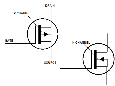 Figure 5. P, N type MOSFET
Vcc control uses P-type MOSFET(IRF4905) due to the action between Source and Drain.(IRF4905 is proper since it has Drain Current for 49A(?). It isn’t less than the current consumption.) So the Jump-Socket will located at upside and connected with Vcc. And pull-down resistor(1k Ω) locates on the other side. The socket acts like pull-up resistor that can change value. It has 0Ω when it’s on pin and ∞Ω when offed. So the each of serial voltage would be 0V and Vcc. Also pull-down resistor’s serial voltage would be Vcc and 0V each. Eventually the MOSFET will turned off when the socket is on pin and turned on when removed.
P-type MOSFET is used to control Vcc and N-type MOSFET is used to control GND. So when designing analogic electrical SW what source you should handle is important. Usually P-type MOSFET is more preferred as GND is used as common source.
Figure 5. P, N type MOSFET
Vcc control uses P-type MOSFET(IRF4905) due to the action between Source and Drain.(IRF4905 is proper since it has Drain Current for 49A(?). It isn’t less than the current consumption.) So the Jump-Socket will located at upside and connected with Vcc. And pull-down resistor(1k Ω) locates on the other side. The socket acts like pull-up resistor that can change value. It has 0Ω when it’s on pin and ∞Ω when offed. So the each of serial voltage would be 0V and Vcc. Also pull-down resistor’s serial voltage would be Vcc and 0V each. Eventually the MOSFET will turned off when the socket is on pin and turned on when removed.
P-type MOSFET is used to control Vcc and N-type MOSFET is used to control GND. So when designing analogic electrical SW what source you should handle is important. Usually P-type MOSFET is more preferred as GND is used as common source.
3.3 Consisting Transformation System
Transformation System makes proper operation voltage for overall system. Due to rated voltage of each parts 7.4V should be supplied with converted power.
Parts Rated voltage Current consumption Odroid U3(MCU) 5V 2A My ahrs+(IMU) 5V 52mA MAX-6Q(GPS) 3.6V 25mA ESP8266(Wi-Fi) 3.3V 0.3A Webcam(CAM) 5V 0.27A
Transformation System only supplies to parts with Navigation Board, MCU and CAM. What we have to focus on is the rated voltage and current consumption of each parts. The above table is that kind of details of MCU, CAM and parts in Navigation Board.
By setting marginal voltage percent as 10%, We can bound MCU, IMU, CAM for 5V ±10% and GPS, Wi-Fi for 3.3V ±10%. So we can choose 5V & 3.3V LDO. The below picture is main datasheet description of MC7805CT(5V LDO) and KIA78R33API(3.3V LDO).
 Figure 6. MC78xx series description
 Figure 7. KIA78Rxx series description
But for the current consumption, output current of LDO should be considered. So two 5V LDO will be used. One for MCU & CAM and the other for IMU so that MCU and other parts operate simultaneously. Generally the sub parts uses the VCC of MCU. But for the stability of power, other parts use independent LDO except CAM. CAM uses MCU’s VCC due to USB connection.
Also attaching capacitors at input and output is necessary. Because on/off action can affect circuits with sudden increment or decrement of current, it can make linked circuits been harmed. So proper capacitors are needed for each LDOs. The datasheet for each parts offer proper capacity of capacitors.
Figure 7. KIA78Rxx series description
But for the current consumption, output current of LDO should be considered. So two 5V LDO will be used. One for MCU & CAM and the other for IMU so that MCU and other parts operate simultaneously. Generally the sub parts uses the VCC of MCU. But for the stability of power, other parts use independent LDO except CAM. CAM uses MCU’s VCC due to USB connection.
Also attaching capacitors at input and output is necessary. Because on/off action can affect circuits with sudden increment or decrement of current, it can make linked circuits been harmed. So proper capacitors are needed for each LDOs. The datasheet for each parts offer proper capacity of capacitors.
3.4 Drawing Lines
For universal system the spec of line doesn’t have to be considered since the small amount of current is used. However, in EPS system all the current consumption of system is integrated so that the huge amount of current is supplied. Without proper line width circuit can be burned and parts can be destroyed. The below table is current budget for overall system.
part current(A) margin(%) current(A) with margin motor 22 10 24.2 MCU 2 10 2.2 IMU 0.052 10 0.0572 GPS 0.025 10 0.0275 Wi-Fi Module 0.3 10 0.33 CAM 0.27 10 0.297 Total 24.647 27.1117
When it comes to each part with small amount of current, special consideration isn’t needed. Usually small connection uses a little current so it can be covered. But it is important when they become integrated and get bigger and bigger.
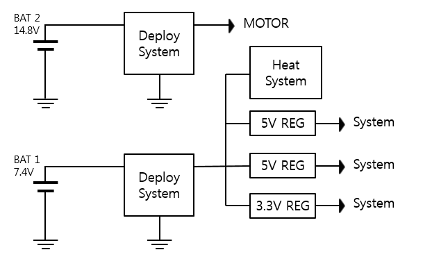 Figure 8. EPS diagram
‘①’ is each regulator’s output lines. First 5V regulator has MCU and supplies 2.2A. Also second regulator has IMU and supplies about 0.06A. 3.3V regulator has GPS and Wi-Fi module and gives about 0.4A. Each value should be considered for each output line width. Also 3A and 1A fuse is attached to each output line due to safety of latter systems.
‘②’ is input lines of each regulators and has one signal input for Heat system. As the regulator has output current sum for 2.66A with margin, we can consider this value as integrated current. Signal for Heat System can be ignored.
‘③’ is power lines for actuator stack and has biggest current in overall system. For 24.2A consumption 14.8V battery power line and output pin of deploy system should have thick line width and thermals.
2015 ARLISS satellite system is built with 10% margin for current. Electrical & electronical system is all implemented with PCBs. So line width is considered as path width and coper width with 1 ounce. PCB implementation will treated in PCB seminar and you can see the details in documents only for PCB.
Figure 8. EPS diagram
‘①’ is each regulator’s output lines. First 5V regulator has MCU and supplies 2.2A. Also second regulator has IMU and supplies about 0.06A. 3.3V regulator has GPS and Wi-Fi module and gives about 0.4A. Each value should be considered for each output line width. Also 3A and 1A fuse is attached to each output line due to safety of latter systems.
‘②’ is input lines of each regulators and has one signal input for Heat system. As the regulator has output current sum for 2.66A with margin, we can consider this value as integrated current. Signal for Heat System can be ignored.
‘③’ is power lines for actuator stack and has biggest current in overall system. For 24.2A consumption 14.8V battery power line and output pin of deploy system should have thick line width and thermals.
2015 ARLISS satellite system is built with 10% margin for current. Electrical & electronical system is all implemented with PCBs. So line width is considered as path width and coper width with 1 ounce. PCB implementation will treated in PCB seminar and you can see the details in documents only for PCB.
3.5 Connectors
Since the other systems work in other board(not in EPS board) transmitting power to other systems is needed. It is done with connectors for direct connection between EPS and other system that power is needed.
Consideration of connectors is similar with drawing lines in amount of current. (We already handled about rated line currents in above ①, ③.) Additionally it considers vibration of satellite and tension for connectors. So vibration test is demanded. But the lack of test environment we use heuristic method. Usually molex connectors are used for small rated current, and terminal block for huge rated current. So we use molex for ①, terminal block for ③, 7.4V battery and 14.8V battery. The below picture is used molex and terminal blocks for EPS.
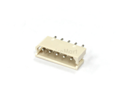
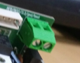
 Figure 9, 10, 11. 5P Molex, 25A Terminal Block, 70A Terminal Block
4.Production
EPS Board
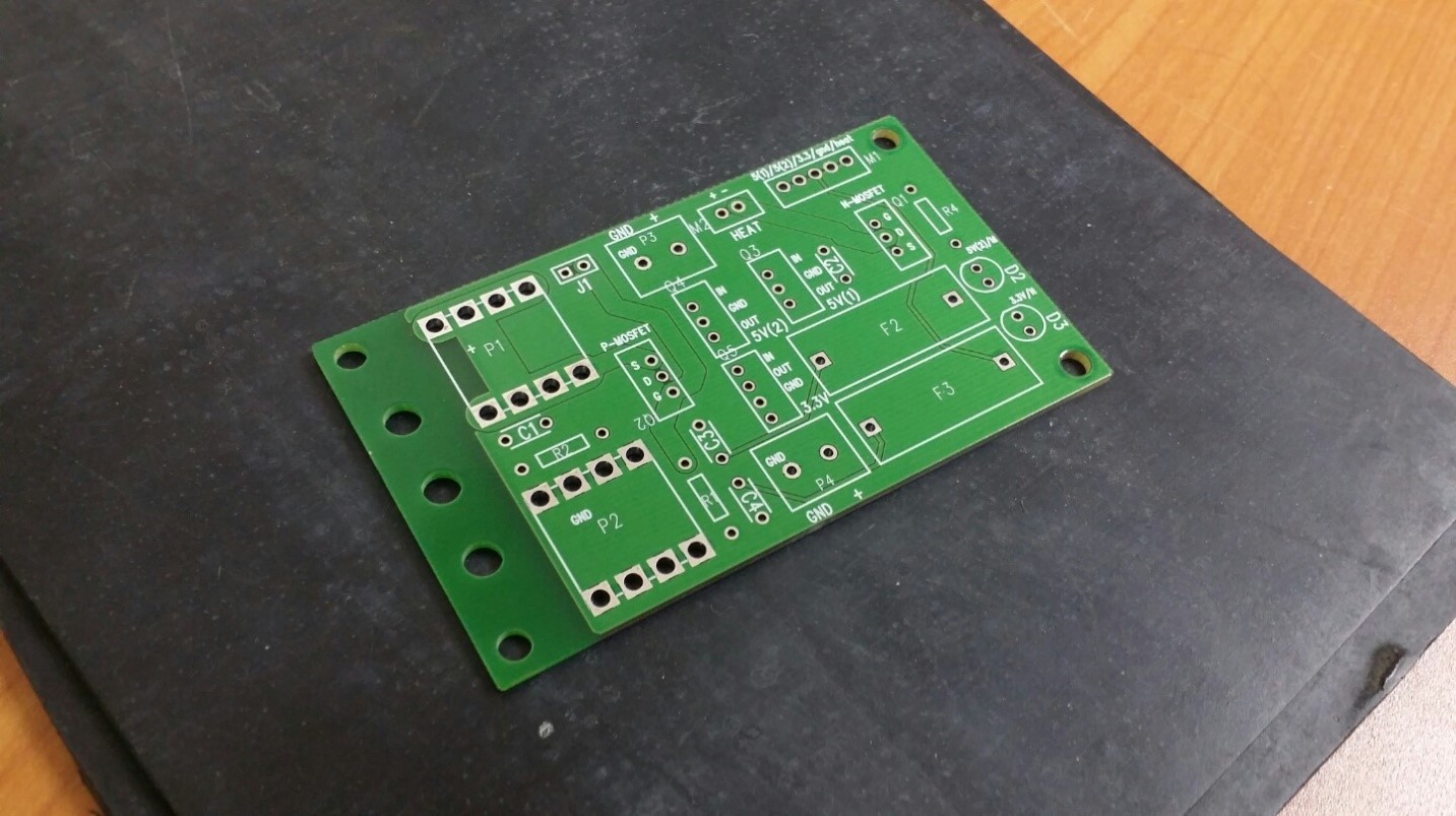 Figure 12. EPS PCB Board
EPS for competition
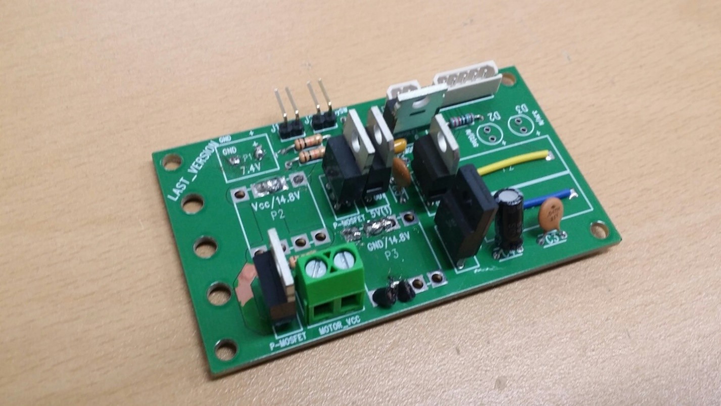 Figure 13. EPS
5.Results
- Arliss Power Budget | Category | Part | Max Power(mW) | Num Margin(%) | Total Power(mW) | | -- | -- | -- | -- | -- | |MCU | Odroid U3 | 10000 | 1 | 10 | 11000 | | COMM. | ESP8266 | 709.5 | 1 | 30 | 922.35 | | CAM | WebCAM | No spec 2 | No spec | |GPS | AKS6H | 82.5 | 1 | 10 | 90.7 | | IMU | myAHRS+ | 260 | 1 |10 | 286 | | Motor | NTM Prop Drive Series 28-30A 800kV | 222000 | 2 | 30 | 577200 | |Total Power(mW)| | | | 589499|
6.Trouble Shooting
- Battery problem There were some strange phenomenon with 11.1V 3S battery. The problem was that MCU turned automatically off only with 11.1V battery. We can use 14.8V battery for overall system but it has many electrical hazardous points. Also we can use 7.4V battery but it cannot make the motors worked. So we make the power binary. As a result, the solution for this problem is using 14.8V for motor and 11.1V for other systems.
- Satellite weight problem ARLISS weight restrict of satellite is 1050g. Because of this weight problem EPS system couldn’t have heavy parts. So two 14.8V battery terminal block, one 7.4V terminal block, all LEDs and all FUSEs are ruled out. Direct soldering is applied instead of terminal blocks and FUSEs but LEDs were simply removed.
7.References
1) MIT Electric Vehicle Team, A Guide to Understanding Battery Specifications, 2008