混控器和执行器
PX4 的系统构架可确保不需要在核心控制器中对不同的机身布局进行任何特殊的处理。
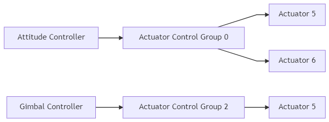
混合意味着接收力的指令(比如: 向右转),然后将这些指令转换成实际的执行器指令来控制电机或者舵机。 对于一个每片副翼都有一个舵机的飞机而言这就意味着控制这两个舵机一个向上偏转,一个向下偏转。 这也适用于多旋翼:向前俯仰需要改变所有电机的转速。
将混控逻辑与实际的姿态控制器分离开来大大提高了程序的可复用性。
控制通道
特定的控制器发送一个特定的归一化的力或力矩指令(缩放至 -1..+1 )给混控器,混控器则相应地去设置每个单独的执行器。 控制量输出驱动程序(比如:UART, UAVCAN 或者 PWM)则将混控器的输出所放为执行器实际运行时的原生单位, 例如输出一个值为 1300 的 PWM 指令。
控制组
PX4 系统中使用控制组(输入)和输出组。 从概念上讲这两个东西非常简单: 一个控制组可以是核心飞行控制器的 姿态,也可以是载荷的 云台 。 一个输出组则是一个物理上的总线,例如 飞控上最开始的 8 个 PWM 舵机输出口。 每一个组都有 8 个单位化(-1..+1)的指令端口,这些端口可以通过混控器进行映射和缩放。 混控器定义了这 8 个控制信号如何连接至 8 个输出口。
对于一个简单的飞机来说 control 0(滚转)直接与 output 0(副翼)相连接。 对于多旋翼而言事情要稍有不同:control 0(滚转)与全部四个电机相连接,并会被整合至油门指令中。
控制组 #0 (Flight Control)
- 0:roll (-1..1)
- 1:pitch (-1..1)
- 2:yaw (-1..1)
- 3:throttle (正常范围为 0..1,变距螺旋桨和反推动力情况下范围为 -1..1)
- 4:flaps (-1..1)
- 5:spoilers (-1..1)
- 6:airbrakes (-1..1)
- 7:landing gear (-1..1)
控制组 #1 (Flight Control VTOL/Alternate)
- 0:roll ALT (-1..1)
- 1:pitch ALT (-1..1)
- 2:yaw ALT (-1..1)
- 3:throttle ALT (正常范围为 0..1,变距螺旋桨和反推动力情况下范围为 -1..1)
- 4:保留 / aux0
- 5:reserved / aux1
- 6:保留 / aux2
- 7:保留 / aux3
控制组 #2 (Gimbal)
- 0:gimbal roll
- 1:gimbal pitch
- 2: gimbal yaw
- 3: gimbal shutter
- 4:保留
- 5:保留
- 6:保留
- 7:保留 (降落伞, -1..1)
控制组 #3 (Manual Passthrough)
- 0: RC roll
- 1: RC pitch
- 2: RC yaw
- 3: RC throttle
- 4: RC mode switch (Passthrough of RC channel mapped by RC_MAP_FLAPS)
- 5: RC aux1 (Passthrough of RC channel mapped by RC_MAP_AUX1)
- 6: RC aux2 (Passthrough of RC channel mapped by RC_MAP_AUX2)
- 7: RC aux3 (Passthrough of RC channel mapped by RC_MAP_AUX3)
此组仅用于定义在 普通操作 期间的 RC输入的映射到具体输出(见 quad_x.main.mix 关于AUX2在混合器中缩放的示例) 在手动 IO 故障安全覆盖事件中(如果 PX4FMU 停止与 PX4IO 板通信), 只有 pitch、yaw和 throttle 这些控制组0定义的映射/混合被使用 (忽略其他映射)。
Control Group #6 (First Payload)
- 0: function 0
- 1: function 1
- 2: function 2
- 3: function 3
- 4: function 4
- 5: function 5
- 6: function 6
- 7: function 7
虚拟控制组
虚拟控制组并不作为混控器的输入量使用,它们将作为元通道(meta-channels)将固定翼控制器和多旋翼控制器的输出传递给 VOTL 调节器模块(VTOL governor module)。
控制组 #4 (Flight Control MC VIRTUAL)
- 0: roll ALT (-1..1)
- 1: pitch ALT (-1..1)
- 2: yaw ALT (-1..1)
- 3: throttle ALT (正常范围为 0..1,变距螺旋桨和反推动力情况下范围为 -1..1)
- 4:保留 / aux0
- 5:保留 / aux1
- 6:保留 / aux2
- 7:保留 / aux3
控制组 #5 (Flight Control FW VIRTUAL)
- 0: roll ALT (-1..1)
- 1: pitch ALT (-1..1)
- 2: yaw ALT (-1..1)
- 3: throttle ALT (正常范围为 0..1,变距螺旋桨和反推动力情况下范围为 -1..1)
- 4:保留 / aux0
- 5:保留 / aux1
- 6:保留 / aux2
- 7:保留 / aux3
输出组/映射
一个产出组是一个物理总线(例如 FMU PWM 输出,IO PWM 输出,UAVCAN 等)。 具有 N (通常为8) 个规范化(-1..+1)的命令端口,可以通过混音器映射和缩放。
混音器文件没有明确定义输出应用的实际 输出组 (物理总线)。 相反,混合物的目的 (例如控制MAIN或 AUX 输出) 从混音器 filename 中推断,并映射到系统中适当的物理总线 startup scripts (尤其是rc.interface)。
这种方法很有必要,因为用于MAIN输出的物理总线并不总是一样的; 它取决于飞行控制器是否有 IO Board(见PX4 Reference Flight Controller Design > Main/IO Function Breakdown) 或使用UAVCAN 进行发动机控制。 启动脚本使用"设备"抽象将混音器文件加载到板子适当的设备驱动器。 如果 UAVCAN 已启用,主混音器将被加载到设备
/dev/uavcan/esc(uavcan) 否则/dev/pwm_output0(此设备已映射给具有I/O 板的控制器的 IO 驱动,且 FMU 驱动程序已映射到未映射的板上)。 Aux 混控器 文件被加载到设备/dev/pwm_output1, 它将映射到 Pixhawk 控制器上拥有 I/O 板子的 FMU 驱动程序。
因为有多个控制组(例如飞行控制、有效载荷等)。 和多个输出组(总线) ,一个控制组可以向多个输出组发送命令。
在实践中,启动脚本只会加载混控器到单个设备 (输出组)。 这是一个配置而不是技术限制; 您可以将主混音器加载到多个驱动器中,例如在UAVCAN 和主引脚上都有相同的信号。
PX4 混控器定义
Mixers are defined in plain-text files using the syntax below.
Files for pre-defined airframes can be found in ROMFS/px4fmu_common/mixers. These can be used as a basis for customisation, or for general testing purposes.
混合文件名称
A mixer file must be named XXXX.main.mix if it is responsible for the mixing of MAIN outputs or XXXX.aux.mix if it mixes AUX outputs.
Mixer Loading
The default set of mixer files (in Firmware) are defined in px4fmu_common/init.d/airframes/. These can be overridden by mixer files with the same name in the SD card directory /etc/mixers/ (SD card mixer files are loaded by preference).
PX4 loads mixer files named XXXX.main.mix onto the MAIN outputs and YYYY.aux.mix onto the AUX outputs, where the prefixes depend on the airframe and airframe configuration. Commonly the MAIN and AUX outputs correspond to MAIN and AUX PWM outputs, but these may be loaded into a UAVCAN (or other) bus when that is enabled.
The MAIN mixer filename (prefix XXXX) is set in the airframe configuration using set MIXER XXXX (e.g. airframes/10015_tbs_discovery calls set MIXER quad_w to load the main mixer file quad_w.main.mix).
The AUX mixer filename (prefix YYYY above) depends on airframe settings and/or defaults:
MIXER_AUXcan be used to explicitly set which AUX file is loaded (e.g. in the aiframe configuration,set MIXER_AUX vtol_AAERTwill loadvtol_AAERT.aux.mix).- Multicopter and Fixed-Wing airframes load pass.aux.mix by default (i.e if not set using
MIXER_AUX). > Tippass.aux.mixis the RC passthrough mixer, which passes the values of 4 user-defined RC channels (set using the RC_MAP_AUXx/RC_MAP_FLAPS parameters) to the first four outputs on the AUX output. - VTOL frames load the AUX file specified using
MIXER_AUXif set, or the value specified byMIXERif not. - Frames with gimbal control enabled (and output mode set to AUX) will override the airframe-specific MIXER_AUX setting and load
mount.aux.mixon the AUX outputs.
Mixer file loading is implemented in ROMFS/px4fmu_common/init.d/rc.interface.
Loading a Custom Mixer
PX4 loads appropriately named mixer files from the SD card directory /etc/mixers/, by preference, and then the version in Firmware.
To load a custom mixer, you should give it the same name as a "normal" mixer file (that is going to be loaded by your airframe) and put it in the etc/mixers directory on your flight controller's SD card.
Most commonly you will override/replace the AUX mixer file for your current airframe (which may be the RC passthrough mixer - pass.aux.mix). See above for more information on mixer loading.
Syntax
Mixer definitions are text files; lines beginning with a single capital letter followed by a colon are significant. All other lines are ignored, meaning that explanatory text can be freely mixed with the definitions.
Each file may define more than one mixer; the allocation of mixers to actuators is specific to the device reading the mixer definition, and the number of actuator outputs generated by a mixer is specific to the mixer.
For example: each simple or null mixer is assigned to outputs 1 to x in the order they appear in the mixer file.
A mixer begins with a line of the form
<tag>: <mixer arguments>
The tag selects the mixer type; 'M' for a simple summing mixer, 'R' for a multirotor mixer, etc.
空的混控器(Null)
A null mixer consumes no controls and generates a single actuator output whose value is always zero. Typically a null mixer is used as a placeholder in a collection of mixers in order to achieve a specific pattern of actuator outputs.
The null mixer definition has the form:
Z:
一个简单的混控器
A simple mixer combines zero or more control inputs into a single actuator output. Inputs are scaled, and the mixing function sums the result before applying an output scaler.
A simple mixer definition begins with:
M: <control count>
O: <-ve scale> <+ve scale> <offset> <lower limit> <upper limit>
If <control count> is zero, the sum is effectively zero and the mixer will output a fixed value that is <offset> constrained by <lower limit> and <upper limit>.
The second line defines the output scaler with scaler parameters as discussed above. Whilst the calculations are performed as floating-point operations, the values stored in the definition file are scaled by a factor of 10000; i.e. an offset of -0.5 is encoded as -5000.
The definition continues with <control count> entries describing the control inputs and their scaling, in the form:
S: <group> <index> <-ve scale> <+ve scale> <offset> <lower limit> <upper limit>
The
S:lines must be below theO:line.
The <group> value identifies the control group from which the scaler will read, and the <index> value an offset within that group. These values are specific to the device reading the mixer definition.
When used to mix vehicle controls, mixer group zero is the vehicle attitude control group, and index values zero through three are normally roll, pitch, yaw and thrust respectively.
The remaining fields on the line configure the control scaler with parameters as discussed above. Whilst the calculations are performed as floating-point operations, the values stored in the definition file are scaled by a factor of 10000; i.e. an offset of -0.5 is encoded as -5000.
An example of a typical mixer file is explained here.
针对多旋翼的混控器
The multirotor mixer combines four control inputs (roll, pitch, yaw, thrust) into a set of actuator outputs intended to drive motor speed controllers.
The mixer definition is a single line of the form:
R: <geometry> <roll scale> <pitch scale> <yaw scale> <idlespeed>
The supported geometries include:
- 4x - quadrotor in X configuration
- 4+ - quadrotor in + configuration
- 6x - hexacopter in X configuration
- 6+ - hexacopter in + configuration
- 8x - octocopter in X configuration
- 8+ - octocopter in + configuration
Each of the roll, pitch and yaw scale values determine scaling of the roll, pitch and yaw controls relative to the thrust control. Whilst the calculations are performed as floating-point operations, the values stored in the definition file are scaled by a factor of 10000; i.e. an factor of 0.5 is encoded as 5000.
Roll, pitch and yaw inputs are expected to range from -1.0 to 1.0, whilst the thrust input ranges from 0.0 to 1.0. Output for each actuator is in the range -1.0 to 1.0.
Idlespeed can range from 0.0 to 1.0. Idlespeed is relative to the maximum speed of motors and it is the speed at which the motors are commanded to rotate when all control inputs are zero.
In the case where an actuator saturates, all actuator values are rescaled so that the saturating actuator is limited to 1.0.
针对直升机的混控器
The helicopter mixer combines three control inputs (roll, pitch, thrust) into four outputs ( swash-plate servos and main motor ESC setting). The first output of the helicopter mixer is the throttle setting for the main motor. The subsequent outputs are the swash-plate servos. The tail-rotor can be controlled by adding a simple mixer.
The thrust control input is used for both the main motor setting as well as the collective pitch for the swash-plate. It uses a throttle-curve and a pitch-curve, both consisting of five points.
The throttle- and pitch- curves map the "thrust" stick input position to a throttle value and a pitch value (separately). This allows the flight characteristics to be tuned for different types of flying. An explanation of how curves might be tuned can be found in this guide (search on Programmable Throttle Curves and Programmable Pitch Curves).
The mixer definition begins with:
H: <number of swash-plate servos, either 3 or 4>
T: <throttle setting at thrust: 0%> <25%> <50%> <75%> <100%>
P: <collective pitch at thrust: 0%> <25%> <50%> <75%> <100%>
T: defines the points for the throttle-curve. P: defines the points for the pitch-curve. Both curves contain five points in the range between 0 and 10000. For simple linear behavior, the five values for a curve should be 0 2500 5000 7500 10000.
This is followed by lines for each of the swash-plate servos (either 3 or 4) in the following form:
S: <angle> <arm length> <scale> <offset> <lower limit> <upper limit>
The <angle> is in degrees, with 0 degrees being in the direction of the nose. Viewed from above, a positive angle is clock-wise. The <arm length> is a normalized length with 10000 being equal to 1. If all servo-arms are the same length, the values should al be 10000. A bigger arm length reduces the amount of servo deflection and a shorter arm will increase the servo deflection.
The servo output is scaled by <scale> / 10000. After the scaling, the <offset> is applied, which should be between -10000 and +10000. The <lower limit> and <upper limit> should be -10000 and +10000 for full servo range.
The tail rotor can be controller by adding a simple mixer:
M: 1
S: 0 2  10000  10000      0 -10000  10000
By doing so, the tail rotor setting is directly mapped to the yaw command. This works for both servo-controlled tail-rotors, as well as for tail rotors with a dedicated motor.
The blade 130 helicopter mixer can be viewed as an example. The throttle-curve starts with a slightly steeper slope to reach 6000 (0.6) at 50% thrust. It continues with a less steep slope to reach 10000 (1.0) at 100% thrust. The pitch-curve is linear, but does not use the entire range. At 0% throttle, the collective pitch setting is already at 500 (0.05). At maximum throttle, the collective pitch is only 4500 (0.45). Using higher values for this type of helicopter would stall the blades. The swash-plate servos for this helicopter are located at angles of 0, 140 and 220 degrees. The servo arm-lenghts are not equal. The second and third servo have a longer arm, by a ratio of 1.3054 compared to the first servo. The servos are limited at -8000 and 8000 because they are mechanically constrained.