利用视觉或运动捕捉系统进行位置估计
可视惯性测距(VIO)和运动捕捉(MOCAP)系统允许载具在全局位置源不可用或不可靠时(例如在室内,或在桥下飞行时)导航。 等等……
VIO 和 MOCAP 都从“视觉”信息中确定飞机的 pose (位置和姿态)。 它们之间的主要区别是框架透视图:
- VIO 使用 板载传感器 从车辆的角度获取姿势数据(见 egomotion)。
- MoCap 使用 离板摄像机 系统在 3D 空间中获取飞机姿态数据(即它是一个外部系统,告诉飞机其姿态)。
Pose data from either type of system can be used to update a PX4-based autopilot's local position estimate (relative to the local origin) and also can optionally also be fused into the vehicle attitude estimation. Additionally, if the external pose system also provides linear velocity measurements, it can be used to improve the state estimate (fusion of linear velocity measurements is only supported by the EKF2).
本主题介绍如何配置基于 px4 的系统,以便从 MoCap/VIO 系统(通过 ROS 或其他 MAVLink 系统)获取数据,更具体地说明如何设置 MoCap 系统,如 VICON 和 Optitrack,以及基于视觉的估计系统(如 ROVIO、SVO 和 PTAM)。
说明因您使用的是 EKF2 还是 LPE 估计器而异。
PX4 MAVLink 集成
PX4 使用以下 MAVLink 消息获取外部位置信息,并将其映射到 uORB 主题:
| MAVLink | uORB |
|---|---|
| VISION_POSITION_ESTIMATE | vehicle_visual_odometry |
ODOMETRY (frame_id = MAV_FRAME_LOCAL_FRD) |
vehicle_visual_odometry |
| ATT_POS_MOCAP | vehicle_mocap_odometry |
ODOMETRY (frame_id = MAV_FRAME_MOCAP_NED) |
vehicle_mocap_odometry |
EKF2 只订阅 vehicle_visual_odometry 主题,因此只能处理前两个消息(MoCap 系统必须生成这些消息才能与 EKF2 配合使用)。 The odometry message is the only message that can send also linear velocities to PX4. The LPE estimator subscribes to both topics, and can hence process all the above messages.
PX4 默认使用 EKF2 估计。 相比 LPE 得到更好的测试和支持,更得到推荐。
消息应在 30Hz(如果包含协方差)和 50 Hz 之间进行流式传输。
以下 MAVLink 视觉消息暂不支持 PX4:GLOBAL_VISION_POSITION_ESTIMATE,VISION_SPEED_ESTIMATE,VICON_POSITION_ESTIMATE
参考机架
PX4 uses FRD (X Forward, Y Right and Z Down) for the local body frame as well for the reference frame. When using the heading of the magnetometer, the PX4 reference frame x axis will be aligned with north, so therefore it is called NED (X North, Y East, Z Down). The heading of the reference frame of the PX4 estimator and the one of the external pose estimate will not match in most cases. Therefore the reference frame of the external pose estimate is named differently, it is called MAV_FRAME_LOCAL_FRD.
Depending on the source of your reference frame, you will need to apply a custom transformation to the pose estimate before sending the MAVLink Vision/MoCap message. This is necessary to change the orientation of the parent and child frame of the pose estimate, such that it fits the PX4 convention. Have a look at the MAVROS odom plugin for the necessary transformations.
ROS 用户可以在下面的 参考机架和 ROS 中找到更详细的说明。
例如,如果使用 optitrack 框架,则本地框架在水平面上具有 和 (x 正面和 z 右),而 y 轴是垂直的,指向上方。 通过如下转换我们可以转换optrack坐标系到NED系中。
x_{mav},y_{mav} 和 z_{mav} 是我们将通过 MAVLink 发送的位置量,然后我们得到:
x_{mav} = x_{mocap}
y_{mav} = z_{mocap}
z_{mav} = - y_{mocap}
在方向方面,保持标量部分 w 四元数,并以相同的方式交换矢量部分 x、y 和 z。 您可以将此技巧应用于每个系统-如果您需要获取 NED 帧,请相应地查看您的 MoCap 输出和交换轴。
EKF2 调参/配置
必须将以下参数设置为将外部位置信息与 ekf2 一起使用(这些信息可以在 QGroundControl > 飞机设置参数 > ekf2 中设置)。
| 参数 | 外部位置估计的设置 |
|---|---|
| EKF2_AID_MASK | Set vision position fusion, vision velocity fusion, vision yaw fusion and external vision rotation accoring to your desired fusion model. |
| EKF2_HGT_MODE | 设置为 Vision 使用视觉作为高度估计的主要来源。 |
| EKF2_EV_DELAY | 设置为测量的时间戳和 "实际" 捕获时间之间的差异。 有关详细信息,请参阅 below。 |
| EKF2_EV_POS_X, EKF2_EV_POS_Y, EKF2_EV_POS_Z | 设置视觉传感器(或 MoCap 标记)相对于机器人的车身框架的位置。 |
重新启动飞行控制器,以便参数更改生效。
调参 EKF2_EV_DELAY
EKF2_EV_DELAY 是相对于 IMU 测量的 Vision 位置估计延迟 。
换句话说,它是视觉系统时间戳和 "实际" 捕获时间之间的差异,将记录的 IMU 时钟("基本时钟" 为 ekf2)。
从技术上讲,如果 MoCap 和(例如)ROS 计算机之间有正确的时间戳(而不仅仅是到达时间)和时间同步(例如 NTP),则可以将其设置为0。 在现实中,这需要一些经验调整,因为整个 MoCap->PX4 链中的延迟是非常特定的。 系统设置完全同步链的情况很少见!
通过检查 IMU 速率和 EV 速率之间的偏移量,可以从日志中获得延迟的粗略估计:
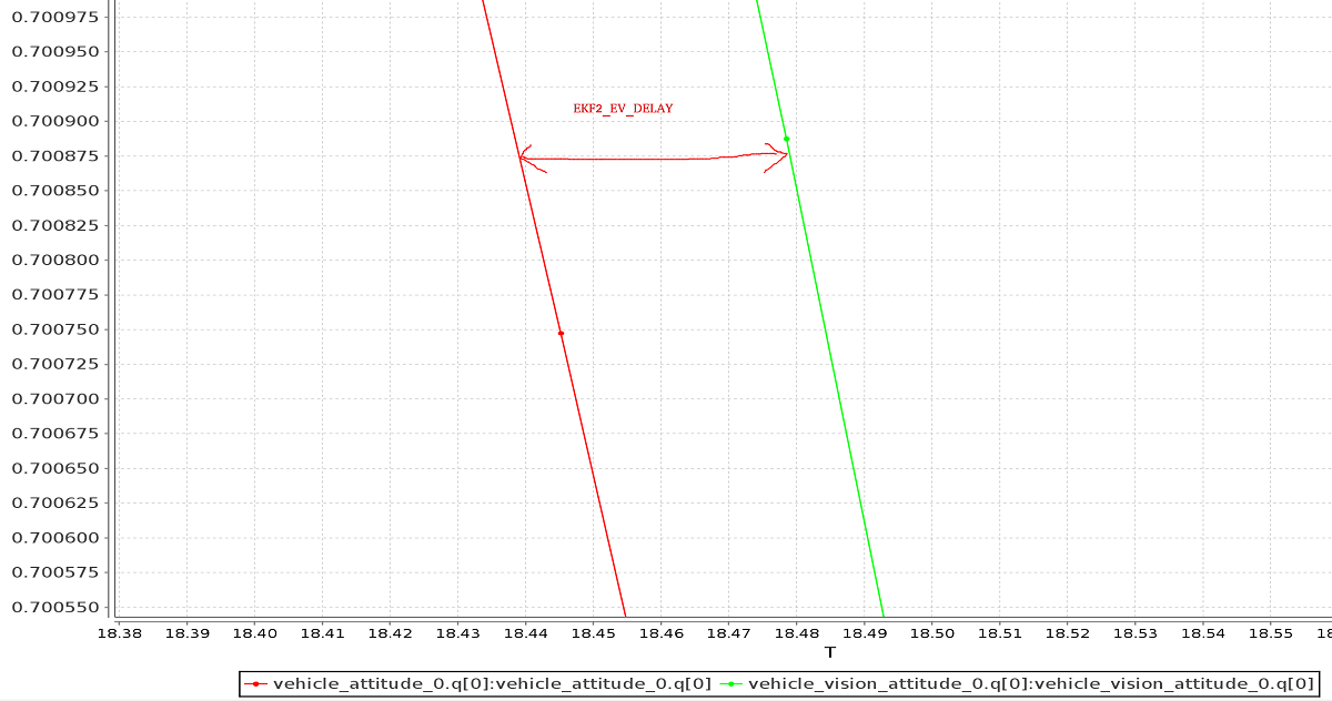
外部数据图表 与 onboard estimate (as above) can be generated using FlightPlot or similar flight analysis tools.
该值可以通过不同的参数一起调整,在动态变化中来保证最低 EKF 。
LPE 调参/配置
首先需要通过设置 SYS_MC_EST_GROUP 参数进行 switch lpe 估计值 。
如果定位
px4_fmu-v2硬件,则还需要使用包含 LPE 模块的固件版本(其他 FMU 系列硬件的固件包括 LPE 和 EKF)。 LPE 版本可以在每个 PX4 版本的 zip 文件中找到,也可以使用生成命令make px4_fmu-v2_lpe从源生成。 有关详细信息, 请参阅 Building the code 。
启用外部位置输入
必须将以下参数设置为将外部位置信息与 LPE 一起使用(这些信息可以在 QGroundControl > > **Vehicle 设置 > 参数 > 本地位置估计 </1 > 中设置)。</p>
| 参数 | 外部位置估计的设置 |
|---|---|
| LPE_FUSION | 如果选中了 fuse 视觉位置 (默认情况下启用),则启用视觉集成。 |
| ATT_EXT_HDG_M | 设置为1或 2,以启用外部标题集成。 将其设置为1将启用视觉,而2则启用了 MoCap heading 的使用。 |
禁用气压计融合
如果从 VIO 或 MoCap 信息中已经提供了高度精确的高度,则禁用 LPE 中的巴洛校正以减少 z 轴上的漂移可能会很有用。
这可以通过 QGroundControl 中通过取消选中 LPE_FUSION 参数中的 *fuse baro</0 > 选项来实现。</p>
滤波噪声参数调参
如果您的视觉或 MoCap 数据非常准确,并且您只希望估计器对其进行严格跟踪, 则应减少标准偏差参数、 LPE_VIS_XY 和 LPE_VIS_Z (用于视觉) 或 LPE_VIC_P (用于 MoCap)。 减小它们会使估计器更加信任外部传入的位姿信息。 您可能需要将它们设置为允许的最小值。
如果性能仍然较差,请尝试增大 LPE_PN_V 参数。 这将使估计器在估计速度时更信任测量值。
使用 ROS
ROS 不是提供外部姿态信息的 required,但强烈建议使用它,因为它已经与 VIO 和 MoCap 系统进行了良好的集成。 PX4 必须已设置如上所示。
将数据输入 ROS
VIO 和 MoCap 系统具有不同的获取姿势数据的方式,并且有自己的设置和主题。
below 涵盖了特定系统的设置。 对于其他系统,请参阅供应商设置文档。
将数据回传给 PX4
MAVROS 具有插件,可使用以下管道从 VIO 或 MOCAP 系统中继可视化估计:
| ROS | MAVLink | uORB |
|---|---|---|
| /mavros/vision_pose/pose | VISION_POSITION_ESTIMATE | vehicle_visual_odometry |
| /mavros/odometry/odom | ODOMETRY (frame_id = MAV_FRAME_LOCAL_FRD) |
vehicle_visual_odometry |
| /mavros/mocap/pose | ATT_POS_MOCAP | vehicle_mocap_odometry |
| /mavros/odometry/odom | ODOMETRY (frame_id = MAV_FRAME_MOCAP_NED) |
vehicle_mocap_odometry |
您可以将上述任何管道与 LPE 一起使用。
如果您使用的是 EKF2,则仅支持 "视觉" 管道。 要将 MoCap 数据与 EKF2 一起使用,您必须 remap 从 mocap 获得的位置信息主题:
- 必须重新映射
geometry_msgs/PoseStamped或geometry_msgs/PoseWithCovarianceStamped类型的 MOCAP ROS 主题,以/mavros/vision_pose/pose。geometry_msgs/PoseStamped主题是最常见的,因为 mocap 通常没有与数据相关的协方差。 - 如果您通过
nav_msgs/OdometryROS 消息获取数据,则需要重新映射数据以/mavros/odometry/odom。
参考框架和 ROS
ROS 和 PX4 使用的本地/世界坐标系和全局框架是不同的。
| 框架 | ROS | PX4 |
|---|---|---|
| 机体 | FLU (x < 0>F</strong>orward、y < 0>L</strong>eft、z < 0>U</strong>p), 通常命名 base_link |
FRD (X Forward, Y Right 和 Z Down) |
| 世界坐标系 | FLU or ENU (X East, Y North and Z Up), with the naming being odom or map |
FRD or NED (X North, Y East, Z Down) |
有关 ROS 框架的详细信息,请参阅 REP105: Coordinate Frames for Mobile Platforms。
Both frames are shown in the image below (FLU on left/FRD on right).
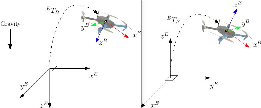
With EKF2 when using external heading estimation, magnetic north can either be ignored and or the heading offset to magnetic north can be calculated and compensated. Depending on your choice the yaw angle is given with respect to either magnetic north or local x.
When creating the rigid body in the MoCap software, remember to first align the robot's local x axis with the world x axis otherwise the yaw estimate will have an offset. This can stop the external pose estimate fusion from working properly. Yaw angle should be zero when body and reference frame align.
利用MAVROS功能包,以上操作会十分简单。 ROS 默认使用 ENU 系, 因此你在MAVROS中所有代码必须遵循ENU系。 如果您有一个 Optitrack 系统, 则可以使用 mocap_optitrack 节点, 其已经发布了一个关于刚体位姿的一个ROS话题。 通过重新映射,您可以直接将其发布在 mocap_pose_estimate 因为它没有任何转换,mavros 将负责 NED 转换。
The MAVROS odometry plugin makes it easy to handle the coordinate frames. It uses ROS's tf package. Your external pose system might have a completely different frame convention that does not match the one of PX4. The body frame of the external pose estimate can depend on how you set the body frame in the MOCAP software or on how you mount the VIO sensor on the drone. The MAVROS odometry plugin needs to know how the external pose's child frame is oriented with respect to either the airframe's FRD or FLU body frame known by MAVROS. You therefore have to add the external pose's body frame to the tf tree. This can be done by including an adapted version of the following line into your ROS launch file.
  <node pkg="tf" type="static_transform_publisher" name="tf_baseLink_externalPoseChildFrame"
        args="0 0 0 <yaw> <pitch> <roll> base_link <external_pose_child_frame> 1000"/>
Make sure that you change the values of yaw, pitch and roll such that it properly attaches the external pose's body frame to the base_link or base_link_frd. Have a look at the tf package for further help on how to specify the transformation between the frames. You can use rviz to check if you attached the frame right. The name of the external_pose_child_frame has to match the child_frame_id of your nav_msgs/Odometry message. The same also applies for the reference frame of the external pose. You have to attach the reference frame of the external pose as child to either the odom or odom_frd frame. Adapt therefore the following code line accordingly.
  <node pkg="tf" type="static_transform_publisher" name="tf_odom_externalPoseParentFrame"
        args="0 0 0 <yaw> <pitch> <roll> odom <external_pose_parent_frame> 1000"/>
If the reference frame has the z axis pointing upwards you can attached it without any rotation (yaw=0, pitch=0, roll=0) to the odom frame. The name of external_pose_parent_frame has to match the frame_id of the odometry message.
When using the MAVROS odom plugin, it is important that no other node is publishing a transform between the external pose's reference and child frame. This might break the tf tree.
特定的系统设置
光学跟踪 MoCap
The following steps explain how to feed position estimates from an OptiTrack system to PX4. It is assumed that the MoCap system is calibrated. See this video for a tutorial on the calibration process.
设置 Motive mocap 软件
- 将无人机的前进方向与 system + x-axiss 对齐
- Define a rigid body in the Motive software。 为机器人指定一个不包含空格的名称,例如
robot1而不是Rigidbody 1 - 启用帧广播和 VRPN 流
- 将 "向上" 轴设置为 z 轴(默认值为 y)
将数据输入 ROS
- 安装
vrpn_client_ros包 - 你可以通过运行在一个单独的话题上得到每一个机体的姿势
  bash
  roslaunch vrpn_client_ros sample.launch server:=<mocap machine ip>
If you named the rigidbody as robot1, you will get a topic like /vrpn_client_node/robot1/pose
重新映射/重新映射位置数据
MAVROS provides a plugin to relay pose data published on /mavros/vision_pose/pose to PX4. Assuming that MAVROS is running, you just need to remap the pose topic that you get from MoCap /vrpn_client_node/<rigid_body_name>/pose directly to /mavros/vision_pose/pose. Note that there is also a mocap topic that MAVROS provides to feed ATT_POS_MOCAP to PX4, but it is not applicable for EKF2. However, it is applicable with LPE.
Remapping pose topics is covered above Relaying pose data to PX4 (
/vrpn_client_node/<rigid_body_name>/poseis of typegeometry_msgs/PoseStamped).
Assuming that you have configured EKF2 parameters as described above, PX4 now is set and fusing MoCap data.
You are now set to proceed to the first flight.
第一次飞行
After setting up one of the (specific) systems described above you should now be ready to test. The instructions below show how to do so for MoCap and VIO systems
Check external estimate
Be sure to perform the following checks before your first flight:
- Set the PX4 parameter
MAV_ODOM_LPto 1. PX4 will therefore stream back the received external pose as MAVLink ODOMETRY messages. - It is recommended to check these MAVLink messages with e.g. the Analyze Widget of QGroundControl. In order to do this, yaw the vehicle until the quaternion of the ODOMETRY message is very close to a unit quaternion. (w=1, x=y=z=0)
- At this point the body frame is aligned with the reference frame of the external pose system. If you do not manage to get a quaternion close to the unit quaternion without rolling or pitching your vehicle, your frame probably still have a pitch or roll offset. Do not proceed if this is the case and check your coordinate frames again.
- Once aligned you can pick the vehicle up from the ground and you should see the position's z coordinate decrease. Moving the vehicle in forward direction, should increase the position's x coordinate. While moving the vehicle to the right should increase the y coordinate. In the case you send also linear velocities from the external pose system, you should also check the linear velocities. Check that the linear velocities are in expressed in the FRD body frame reference frame.
- Set the PX4 parameter
MAV_ODOM_LPback to 0. PX4 will stop streaming this message back.
If those steps are consistent, you can try your first flight.
Put the robot on the ground and start streaming MoCap feedback. Lower your left (throttle) stick and arm the motors.
At this point, with the left stick at the lowest position, switch to position control. You should have a green light. The green light tells you that position feedback is available and position control is now activated.
Put your left stick at the middle, this is the dead zone. With this stick value, the robot maintains its altitude; raising the stick will increase the reference altitude while lowering the value will decrease it. Same for right stick on x and y.
Increase the value of the left stick and the robot will take off, put it back to the middle right after. Check if it is able to keep its position.
If it works, you may want to set up an offboard experiment by sending position-setpoint from a remote ground station.